Transport Example
All these worked examples are provided in the EXAMPLES directory in Simul8. All transport example file names begin with “Transp”.
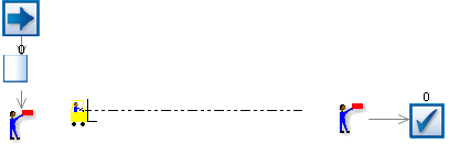
Stage 1
Uses:
- One Path
- One Vehicle
- 2 Loaders
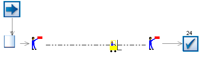
The finished simulation should look like this:
Start by creating a Vehicle Class (this will automatically create a Path Network and one path because all Vehicle Classes must belong to a Path Network, and there is not much point in having a network of paths that contains no paths.
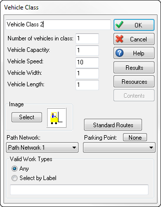
Click the Vehicle button on the Advanced Building Objects tab in the Simulation Drawing Panel.
This creates a new Vehicle class and one Vehicle within that class. It also opens the Vehicle Class dialog. This dialog can also be viewed by clicking on any of the Vehicles in the class on the simulation window.
When the dialog is opened by clicking on an individual Vehicle its CONTENTS button is enabled so that the Work Items currently carried on the Vehicle can be inspected.
Click OK back to the main screen.
The default icon for a Vehicle is a fork lift. The path is shown as a dotted line when Simul8’s Route Arrow button is down. (Paths are not shown as the simulation runs).
Create a Start Point, Queue and Loader (the Loader create button is under the Continuous Building Objects tab in the Simulation Drawing Panel).
Connect them together with routing arrows.
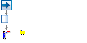
Create a 2nd Loader at the other end of the path, and link it to a End Point.
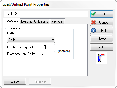
Click on Loader 2 and choose its location tab.
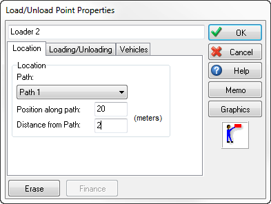
Simul8 has automatically connected it to the only path available but we also have Loader 1 at position 0 (this is 0 feet or meters from one end of the path). Change the Position on Path 1 to 20 (the default length of a path) so that this second Loader is connected to the other end of the path).
Click OK back to the main screen and run the simulation.
The Vehicle transports Work Items from Loader 1 to Loader 2.
Why was the work taken to Loader 2? To make it very easy to build Simul8 simulation with paths and Vehicles there is a default rule that work arriving at a Loader will be taken to any Loader that has an out going routing arrow.
Stage 2
Uses:
- 3 Loaders
- Jobs Matrix for Routing control
The finished simulation:
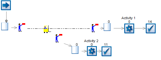
Use the STAGE 1 simulation and add a Queue and Activity between Loader 2 and the End Point:
Then add a third Loader that also feeds a Queue, Activity and End Point.
Connect the Loader to position 10 on the path.
Now use the Job Matrix to define where work requiring Job 1 and 2 needs to go:
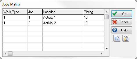
(Double click the Location cells to be able to select from a list of Activities). The timing column is not used in this example.
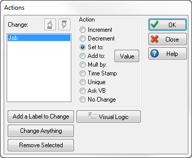
At the Start Point use Actions to set the JOB Label to either 1 or 2 (randomly) like this:
- Click the Start Point
- Click Actions
- Click Choose a Label to change
- Click New and create a Label called JOB, return to the actions dialog.
- Click SET TO: and then choose ROUNDED UNIFORM for the distribution of values and set the “upper bound” to 2.
This means 50% of the work will have the JOB Label set to 1 and 50% will have the JOB Label set to 2.
Click OK back to the main screen and run the simulation.
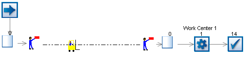
See that the Vehicle goes to Loader 2 and Loader 3 (it automatically works out what Loader feeds the Activity that is relevant for the job - as defined in the Jobs Matrix).